41 civil 3d cut and fill labels
Cut and Fill color map in Civil 3D - cadpanacea.com Make two Expressions Go to Settings > Surface > Label Styles > Spot Elevation. Right click on Expressions and Choose New. Give it a name of "move if positive" In the Expression field, enter IF ( {Surface Elevation}>0,50000,0) Copy this string to the clipboard and press OK Create another new Expression Give it the name "move if negative" Civil Labeler - docs.bentley.com Civil Labeler. You can access this tool from the following: Drawing Production > Labels. It provides an out of the box Civil Labeler.xml file. The following configuration variable is set by default: CIVIL_LABELER_XMLFILE. You can add new Labels to this XML or create your own XML.
k Civil 3D 2021: Fundamentals drawing cole 5. A Quick ... a. Hide b. Show 8 C. Data Clip d. Outer 9. Which of the following is not a surface label that is available out of the box in the Autodesk Civil 3D software? a. Contour Labels b. Spot Elevation Labels c. Slope Labels d. Cut/Fill Labels

Civil 3d cut and fill labels
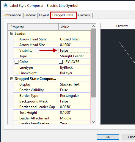
Calculating Average End Area Cut & Fill Volumes using Civil 3D Calculating Average End Area Cut & Fill Volumes using Civil 3D. In the old days; average end area cut and fill volumes were calculated manually from paper cross sections representing a proposed roadway design. Today, using Civil 3D, we can extract average end area volumes with only a couple clicks of the mouse. Label Styles | Civil 3D 2020 | Autodesk Knowledge Network Create a Surface Spot Elevation label style named "Cut Fill." In the Label Style Composer dialog box, on the Layout tab, change the Name property of the label component to "fill." Change its color to Green. Edit the text component and change the Sign Modifier to Hide Negative Value. Volme grid map with cut fill labels - Civil 3D & LDD ... I am trying to create a volume grid map showing cut fill elevation differences at the grid corners and labels in each grid square stating how much cut fill is in that square. I created 2 tin surfaces, Existing Ground Surface and As Made Surface after excavation. I then created a Tin Volume Surface.
Civil 3d cut and fill labels. Civil 3D surface analysis: what are its capabilities ... Civil 3D surface analysis: elevations. This is one of the most used analysis types, especially when it comes to cut and fill. In a similar way to the previous analysis, we can set a number of ranges with different colours. Surface Modeling for Infrastructure Design - Cut and fill ... Open the corridor Properties, and on the Information tab, select Automatic Rebuild. Select the corridor in the drawing, right-click and choose Update Automatically. Select the corridor in Prospector, right-click, and choose Rebuild - Automatic. Select the corridor in the drawing, right-click, and choose Rebuild Automatic. Express yourself using expressions in Civil 3D 5) Create a label style that has 2 components, Cut and Fill text. These components reference the Surface Elevation, but in the text height property, you will set the corresponding expression (Cut/Fill). 6) Change the CUT component color to RED. 7) Change the FILL component to BLUE. 8) Test this out by using your new label style to label a surface!! Civil 3D Tip: Adding Section Labels to Section Views ... 1. Ribbon >> Home tab >> Create Design Panel >> Section Views >> Project Objects To Multiple Section Views 2. Select a section view group. 3. The Project Objects To Multiple Section Views dialog will appear. 4.
AutoCAD Civil 3D Tutorials - help.autodesk.com AutoCAD Civil 3D. The tutorial exercises are organized in a logical sequence, based on how you typically work with the different types of features. However, you may complete the exercises in any order you choose. After you begin an exercise, you should complete the steps in the order presented. PDF CADD Users Manual - Appendix 7, dated August 2019 - California Civil 3D Style (Survey Figure or Point) Feature Description Feature Attributes Layer Linetype or Block ... Marker, Label rd_SURFACE-POINT Continuous 2 0.012 ... surface for both cut and fill. Line rd_SLOPE-CATCH Continuous 15 0.012 Creating Cut/Fill Volume Points or Labels in Civil 3D ... When you need to show cut and fill values at specific points within Autodesk AutoCAD Civil 3D, first you will need to create a volume surface. Place the desired points (or labels) which have a label style which shows the elevation, using the volume surface as the selection when prompted. Welcome to the AutoCAD Civil 3D Tutorials Each tutorial set contains exercises that are designed to explore the various features of AutoCAD Civil 3D. The tutorial exercises are organized in a logical sequence, based on how you typically work with the different types of features. However, you may complete the exercises in any order you choose.
PDF Cut/Fill Spot Labels - AMS Workplace • Change the Label type to Spot Elevation. • Change the Label Style to the one just created. • Click Add and place several labels to verify the functionality. NOTE: In Civil 3D you must have a TIN volume surface created to properly place Cut and Fill Spot Elevations. Rte 46 West, Bldg. Cut and Fill volumes - OpenRoads | OpenSite Wiki ... Can I get a quick information about the cut and fill for existing terrain and a surface in OpenRoads? Answer : The "Create Cut and Fill Volumes" tool calculates cut and fill volumes between two surfaces and creates a 3D mesh solid with volume attributes. The volumes can be viewed in "Properties" or "Elemen Information". Steps : 1. Cut Fill (3D Analyst)—ArcGIS Pro | Documentation Illustration CutFill_3d (Before_Ras, After_Ras, OutRas) When the Cut Fill operation is performed, by default, a specialized renderer is applied to the layer that highlights the locations of cut and of fill. The determinant is in the attribute table of the output raster, which considers positive volume to be where material was cut (removed), and negative volume where material was filled (added). Tips - EnvisionCAD AutoCAD Civil 3D 2018 Tip: Use Civil 3D Line Label Styles to Annotate Utility Linetypes We've all run into this situation before. We have some utility lines drawn that use text in the linetype and the lines are either too short or are at a…

Creating a Grid Volume Surface
Plot Long Sections - Civil Survey Solutions First: Select the Civil 3D Profile, Profile Style to apply to the Existing Surface, then pick [OK]. Second: Select the Civil 3D Profile, Profile Style to apply to the Design surface, then pick [OK]. Third: Select the Civil 3D Profile View, Profile View Style to apply for the Long Section, then pick [OK]. Fourth: Select the Civil 3D Profile View, Band Style to apply to the Long Section, then ...

Learning Civil 3D: Adjusting Individual Labels in Civil 3D
Using Civil 3D to Create a Cut & Fill Earthwork Exhibit ... Once these areas have been defined, a custom spot elevation label style could be used to identify the amount of cut and fill going on in these areas. The best part is that the colorization and annotations remain dynamic to the model. Any changes made to the design will automatically be reflected in your earthwork visualization.

The Civil 3D Experience: Isopachyte and Surface Analysis Tools
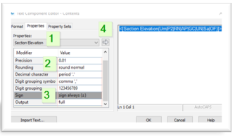
Express Yourself: Using Expressions in Civil 3D | AUGI ... Create a label style that has two components: Cut and Fill text (see Figure 7). These components reference the Surface Elevation, but in the text height property, you will set the corresponding expression (Cut/Fill). Change the CUT component color to RED. Change the FILL component to BLUE. Figure 7

Civil 3D Reminders: Section Labels of Surface
Video: Create Cut Fill Volumes tool - OpenRoads | OpenSite ... The objects in the civil model are compared based on the "Volume Option" in the assigned Feature Definition in order to calculate the cut and fill volumes. The video below discusses basic cut and fill volumes using the Existing , Design , Subgrade , and None Volume Options.
Creating Cut/Fill Volume Points or Labels in Civil 3D - IMAGINiT Civil Solutions Blog
GBUG - Ground Breakers User Group: Cut and Fill Surface Labels The following steps will create the Surface Label Style that will display the Cut labels in RED with a negative symbol and the Fill labels in GREEN: 1. Once the Settings tab is selected you must expand the Surfaces>Label Styles>Spot Elevation trees and right-click to create a NEW style.
AutoCAD Civil 3D 2018 Tip: Use Civil 3D Line Label Styles to Annotate Utility Linetypes ...
Making CUT/FILL Maps in AutoCAD Civil 3D | Part II | ZenTek To begin, let's create the label style we'll need for Cut/Fill mapping. Go to Toolspace > Settings> Surface > Label Styles > Spot Elevation and right-click to create a new style (below). We'll call it CUT-FILL. Next, click on the "Layout" tab and delete the default text entities there.

Zooming In: BIM Modeling for Civil Engineering | Gresham, Smith and Partners
Band and Code Set Styles (CAD Clinic: Civil 3D Tutorial ... A style defines a band's labeling components. After identifying a band type and style, click the Add button to add the type and style to the band set. To remove a style from a band, select the band and click the red X. The arrows move a selected band up or down the list of bands; this action sets the band order in the drawing.

Solved: Civil 3D Labels in viewport too small. BUUUUGGG!!! - Autodesk Community
Solved: cut/fill surface labels - Autodesk Community This method is not really needed as this works well (just been using it today) neilyj (No connection with Autodesk other than using the products in the real world) AEC Collection 2022 UKIE (mainly Civil 3D UKIE and IW) Win 11 Pro x64, 500Gb SSD, 2Tb HDD

Earthwork Plan Production | Autodesk AutoCAD Civil 3D 2020 - Earthwork Calculations
Civil 3D_Cut & Fill Exhibit Labels - YouTube This video will take the Cut & Fill Exhibit we previously created and show you how to add some extended data labels. We review creating the label so that it references 3 different surfaces and...

Pin on CAD/GIS
Creating Cut/Fill Labels for a Volume Surfaces in Civil 3D ... Creating Cut/Fill Labels for a Volume Surfaces in Civil 3D - YouTube Learn how to create one Label Style to easily display the cut or fill depth in a Volume Surface by using Label Expressions.-...
Civil 3D - Create Section Profile Label Style – Cadline Community
Volme grid map with cut fill labels - Civil 3D & LDD ... I am trying to create a volume grid map showing cut fill elevation differences at the grid corners and labels in each grid square stating how much cut fill is in that square. I created 2 tin surfaces, Existing Ground Surface and As Made Surface after excavation. I then created a Tin Volume Surface.

More on Civil 3D Labels (CAD Clinic: Civil 3D Tutorial) | Cadalyst
Label Styles | Civil 3D 2020 | Autodesk Knowledge Network Create a Surface Spot Elevation label style named "Cut Fill." In the Label Style Composer dialog box, on the Layout tab, change the Name property of the label component to "fill." Change its color to Green. Edit the text component and change the Sign Modifier to Hide Negative Value.

Artillery Cross Cannon Clip Art Download 545 clip arts (Page 1) - ClipartLogo.com
Calculating Average End Area Cut & Fill Volumes using Civil 3D Calculating Average End Area Cut & Fill Volumes using Civil 3D. In the old days; average end area cut and fill volumes were calculated manually from paper cross sections representing a proposed roadway design. Today, using Civil 3D, we can extract average end area volumes with only a couple clicks of the mouse.
Masking Labels in Autodesk Civil 3D - IMAGINiT Civil Solutions Blog

Assembly Labels in Civil 3D - YouTube

One Spot Elevation For Multi Surfaces in Civil 3D – Fingerprintvideos
Post a Comment for "41 civil 3d cut and fill labels"